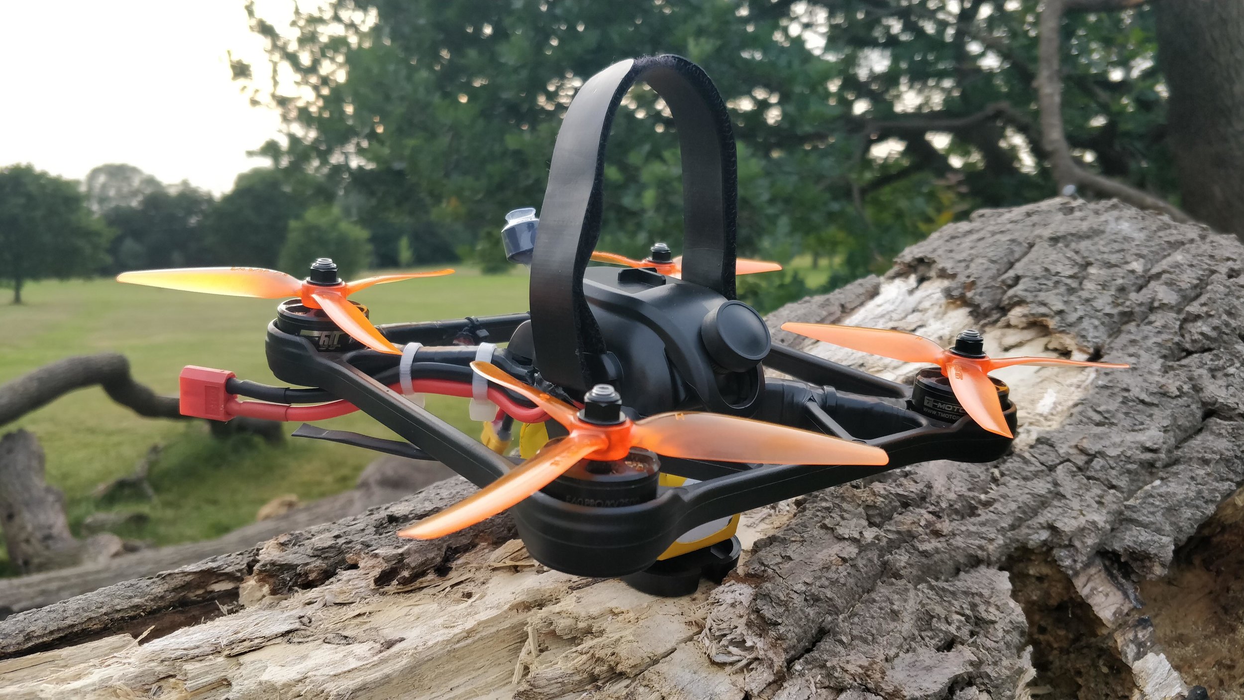
Hello, so the main reason for this build was that I broke my previous frame and this was laying around since I received it in last Drone Drop box.
The only other thing I needed was a 4-in-1 ESC, which after a quick research I decided to go with Holybro Tekko32 35A 4-in-1 BLHeli32 ESC which was supposed to be the best when it comes to noise.
First of all I must say this was the longest builds ever, because of the limited space and that bulky ESC that wouldn't fit into the frame and under the canopy. So perfect planning was the key here. I also wanted to use SP Racing F4 EVO flight controller that was laying around in my spares box, but after realising that it doesn't have an OSD and adding next board is not an option (because of the limited space inside the frame) I had to reuse Omnibus F4 Pro V2 board from a previous build.
Motor holes
Another problem was with the motor holes not being aligned with the motors, as if someone intentionally designed them the other way around. Not sure who to blame (TBS or T-motor) as on other frames holes were universal so I could fit any motor and never expected this would be an issue here. At the end I used an arm from some broken frame and bolted it to the holes in Oblivion and this gave me a template to drill them correctly.
Planning
First thought was to stack everything up where ESC would be on the bottom, turned upside down (so I'd have to solder motors from underneath) with mattery connector sticking out of one of the sides, then Flight Controller, next Receiver and bit higher spacers for the VTX.
This looked like it would fit and should be fine, but I didn;t like the idea of soldering motor cables from underneath the frame, which would also leave a lot of space between bottom of the frame and the ESC, as ESC would have to be high enough so that the battery straps are not being pushed by battery pads and the connector on the ESC.
This gave me an idea to actually place Receiver into that space.
So while doing so I also turned ESC upside down, so I have all the motor pads exposed from the top - for easier soldering. This looked like a success so I started soldering everything together.
Because I have moved Receiver to the bottom of the stack it made some space for the capacitor, and also decided to solder AXII antenna directly to the VTX.
This was all nicely fitting under the canopy, which I had to cut a little to acomodate battery pads that were sticking out at the side of the frame, and the ESC connector with it's cables on the other side.
Unfortunately after plugging it in, there was a lot of noise on the OSD display, and friends suggested to ground VTX and other unused components with additional wires, or use LC filter.
The real build
Back to the drawing board... I happened to have some different PDBs, and this specific Matek one was very thin (Matek Power Hub) so I thought I would stick it under the 4-in-1 ESC and also remove connector from that ESC and solder wires directly to it - to save space, meaning I could get everything about 0.5 centimeter lower.
Preparing receiver
I am big fan of liquid electrical tape - so called Plasti Dip - which I use pretty much on anything.
Wiring motors
Reusing motors from a previous build, where one of them was broken and a replacement just arrived.
Preparing PDB
Again, using Plasti Dip and a hot glue to hold wires where I wanted them to go.
Removing ESC Connector
Only needed to wire 4 signal wires and the telemetry.
Stacking everything up
First goes the PDB, mounted on some rubber washers, then another set of washers (bit higher ones) with the ESC, next soft mounted Flight Controller, next is VTX on one side and lastly a loose Receiver. All coated with Plasti Dip. With his setup I didn't have any noise with the video feed, but I added capacitor anyways with intention to place it outside on one of the arms.
Finishing touches
Last thing to do now was to mount capacitor, buzzer and antena so they are not getting into the way of propellers. Also put a 12AWG cable with XT60 connector instead of the temporary one that was on there from the beginning.


